![favicon_GI.png]](https://knowledge.gantner-instruments.com/hs-fs/hubfs/favicon_GI.png?width=40&height=40&name=favicon_GI.png)
A Q.station controller can communicate with CAN bus devices for real-time test and measurement data acquisition using CAN 2.0A or CAN 2.0B. Configure CAN interfaces and signals in GI.bench, manually map CAN messages or import DBC files, verify 120 Ω bus termination, and calculate bus load to maintain reliable communication.
What Is CAN Bus Communication?
CAN Bus Interface Options for Q.station Controllers
How to Connect a Q.station Controller to a CAN Bus
How to Read CAN Bus Messages in GI.bench
How to Write CAN Bus Messages in GI.bench
How to Export a CAN DBC File from GI.bench
How to Import a CAN DBC File into GI.bench
How to Calculate CAN Bus Load and Message Rates
What Is CAN Bus Communication?
The Controller Area Network (CAN) bus is a robust serial communication protocol designed for reliable, real-time data exchange between distributed devices. Originally developed for automotive applications, CAN bus is now widely used in industrial automation, test and measurement systems, and embedded control applications.
CAN bus enables multiple devices to communicate over a shared network without the need for a central host, providing efficient data transfer, high noise immunity, and built-in error detection mechanisms to ensure reliable operation.
CAN Bus Interface Options for Q.station Controllers
The Q.station X controller is equipped with one CAN 2.0 port, while the Q.station 101 provides two CAN 2.0 ports. Both controllers support CAN 2.0A and CAN 2.0B communication with baud rates of up to 1 Mbps.
Additional CAN interfaces can be added to the Q.station X via its USB ports using a compatible USB-to-CAN adapter. (e.g. PCAN-USB).
How to Connect a Q.station Controller to a CAN Bus
CAN Bus Connectors and Pin Assignments
Q.station 101
On the Q.station 101, the CAN bus is connected to the available screw terminals on the controller.

Q.station X
Q.station X recommended mating connector: LEMO FGG.00.302.CLAD30Z

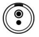
- Top pin: CAN Low
- Bottom pin: CAN High
PCAN-USB adapter
Connector pin assignment according to specification CiA 106.
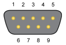
D-Sub Connector
|
Assignment |
Pin |
|
CAN_V+ (optional) |
1 |
|
CAN_Low |
2 |
|
CAN_High |
7 |
|
CAN_GND |
3, 6 |
CAN Bus Cabling and Shielding Requirements
We recommend using only shielded CAN bus cables, with the shield connected directly to the control cabinet frame. The shield acts as a Faraday cage, protecting the CAN twisted pairs from electrical noise. For effective shielding, it must be connected to an earth (GND) potential.
Gantner Instruments offers 2 types of CAN bus cable compatible with the Q.station X.
CAN bus cable with 120 Ω bus termination
- Article no. 603320, 3 m, LEMO to flying leads
CAN bus cable without bus termination
- Article no. 799138: 1 m, LEMO to flying leads
- Article no. 471626: 3 m, LEMO to flying leads
- Article no. 799037: 1 m, LEMO plugs on both sides
CAN Bus Termination: 120 Ω Resistor Requirements
A CAN bus termination (120 Ω each) must be installed at both physical ends of the network. This can be achieved using external 120 Ω resistors connected between the CAN High and CAN Low lines at each endpoint.
The CAN port on the Q.station X controller is not internally terminated, allowing it to be daisy-chained with other CAN devices on the network.
The CAN port is located behind the controller’s galvanic isolation. As a result, a resistance may be measured across the CAN High and CAN Low pins. This is normal and does not indicate a fault.
How to Read CAN Bus Messages in GI.bench
CAN signals are mapped to the controller through virtual variables, enabling flexible integration and processing.
For importing CAN signals from a DBC file, please refer section Importing CAN Configuration Data.
-
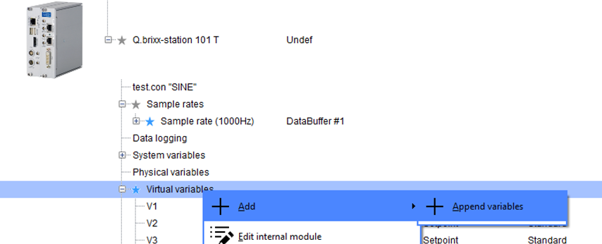
Right-click Virtual variables and select Add > Append variables.
-
Enter the number of new variables to create and select OK.

-
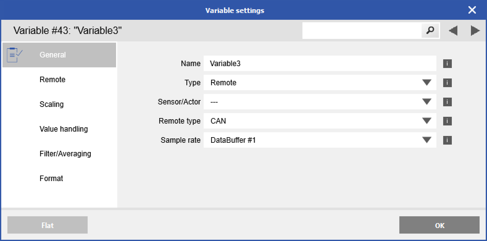
Double-click the newly created variable to open the Variable settings. Enter the desired name and change the Type to Remote and Remote type to CAN.
-
In the Remote settings, select the Port and enter the CAN channel information.
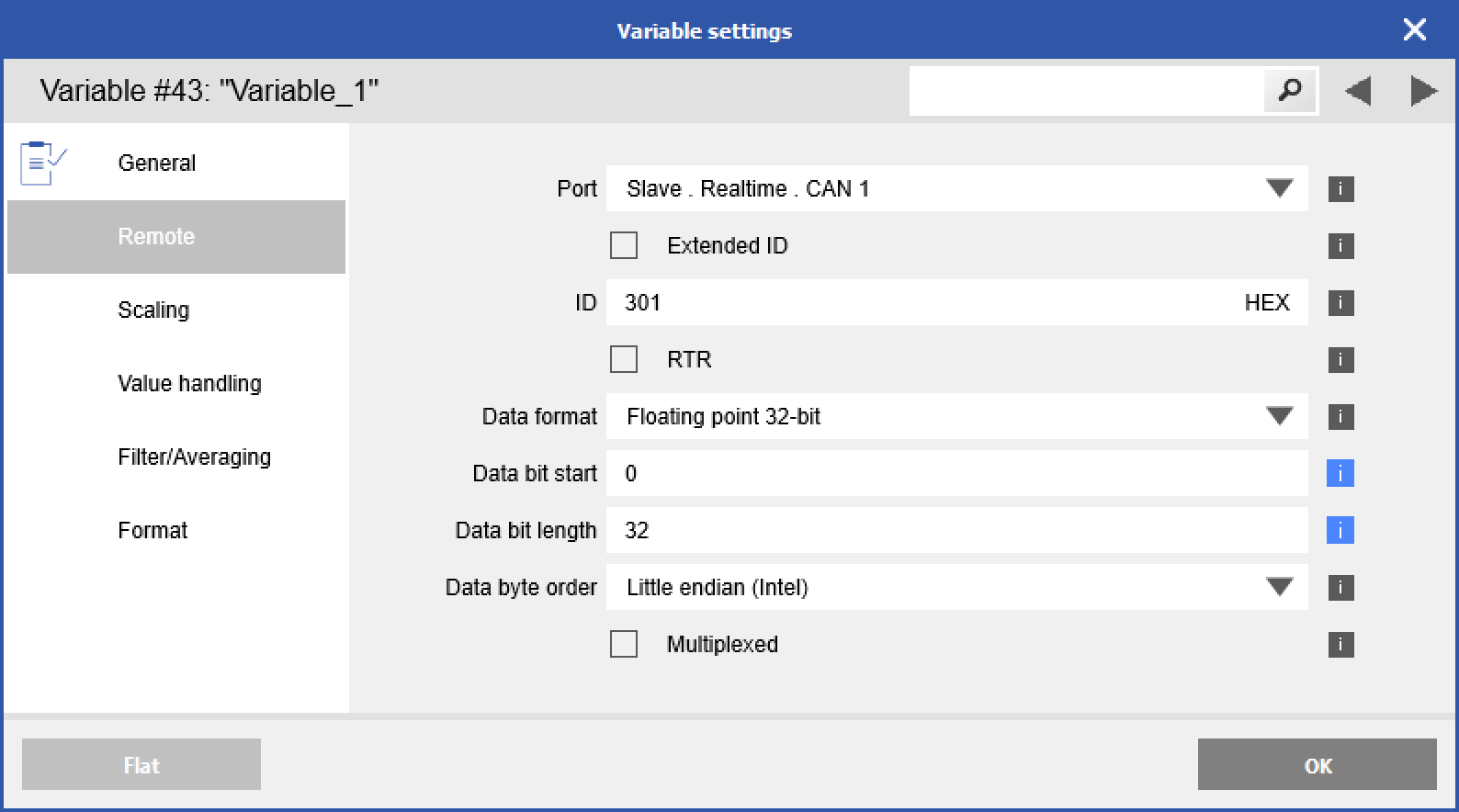
Port
CAN 1 is the onboard CAN interface of the Q.station X (additional CAN interfaces can be connected via USB).
ID
The base ID is max. 11 bit (Hex 7FF), and the extended ID is max. 29 bit (Hex 1FFFFFFF).
Data format
Defines the format of the data in the CAN message, this has to be a valid format to interpret the data correctly.
Data bit start
A CAN frame consists of max. 64-bit of data and can include multiple CAN messages (for example, 2x 8-bit, 1x 16-bit, and 1x 32-bit messages), with this parameter the start bit of the message to read into the CAN frame is defined.
Data bit length
The maximum bit length of a CAN message is defined by the selected CAN data format but can also be less, for example: if the CAN data format is 16-bit, and the bit length is only 5, the missing bits will internally be filled up, or cut off to be able to convert it correctly.
Data byte order
The standard byte order of a CAN message is Little-endian (Intel), to switch the byte order select Big-endian (Motorola).
-
When complete, click OK. Make sure to write any changes to the controller by clicking Write in the Configuration toolbar.

How to Write CAN Bus Messages in GI.bench
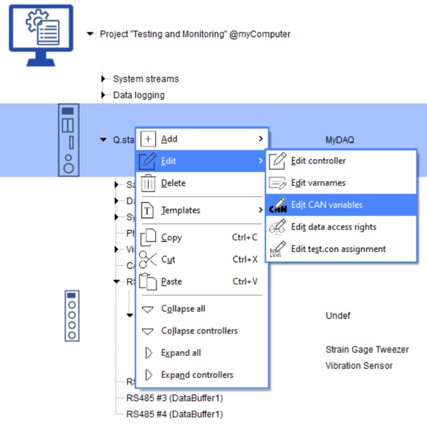
- In GI.bench, right-click on the controller and go to Edit > Edit CAN Variables.
-
The following window will open. Here, you can choose whether the available variables should be written to one or, if multiple are available, several CAN interfaces.
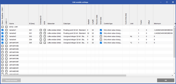
The Name and CAN ID can be freely assigned. Note that names are limited to 20 characters or fewer. The data type can be selected either to match the requirements of the receiving device or to minimize data size, allowing more channels to be transmitted over the CAN interface.
Caution: The Minimum and Maximum values apply to the unscaled raw value of the selected data type. For example, if the Maximum is set to 1000 and a scaling factor of 0.1 is applied, the channel will only display values up to 100. Note that adjusting the scaling does not automatically update the Minimum and Maximum values. This can result in values being clipped due to an unintentionally restricted range.
Navigating the CAN Variable Settings window:
Using the mouse:
- The first click selects a cell.
- The second click either opens the dialog or checks the selected cell(s).
- Shift + Click allows you to select multiple cells.
Using the keyboard:
- Use the arrow keys to navigate between cells.
- Press Enter to open the dialog or check the selected cell(s).
- Use Shift + Arrow keys to select multiple cells.
- If multiple cells are selected in the same column, you can move the selection horizontally across columns using the left and right arrow keys.
Example: The CAN Variable Settings window displays the structure of the CAN IDs and highlights potential issues such as overlaps: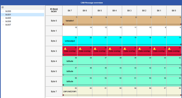
Multiplexed channels can also be visualized in the overview: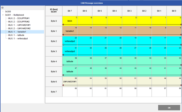
Creating a .DBC file includes the CAN outputs defined in this interface. Configuring CAN outputs does not increase the number of variables in the controller.
How to Export a CAN DBC File from GI.bench
The CAN configuration can be exported as a .DBC file for import into an external device. All CAN inputs and outputs, whether remote variables or configured through the CAN variable settings interface, will be included in the .DBC file.
This feature is only possible with a licensed GI.bench version in expert mode
-
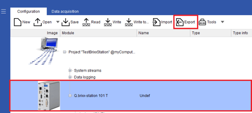
Highlight the controller and click Export.
-
Select CAN DBC file from the list and click OK.
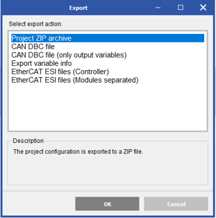
Selecting the “Only Output Variables” option will list only CAN variables transmitted by the Q.station. The “CAN DBC File” option lists both inputs and outputs.
-
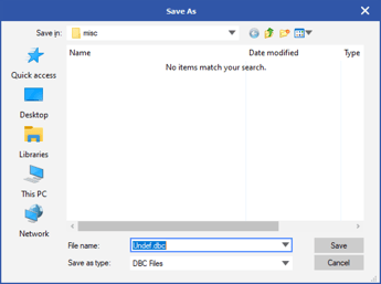
Provide the DBC file name and save it at the desired location.
How to Import a CAN DBC File into GI.bench
This feature is only possible with a licensed GI.bench Version in expert mode
-
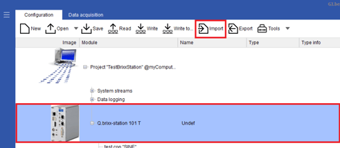
Highlight the controller in the project window and click Import.
-
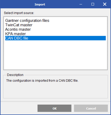
Select CAN DBC file from the list and click OK.
-
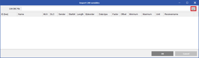
Click the three dots icon at the top-right corner to select a DBC file to import.
-
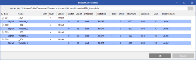
Select the CAN signals to import (use Ctrl + click for multi-selection).
-
The variables will be automatically added as Remote CAN virtual variables.
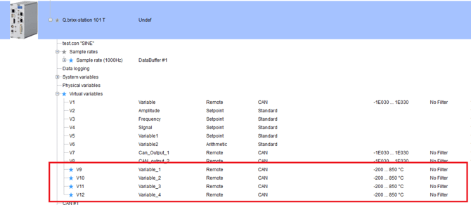
If the imported signal names exceed 20 characters, the user can choose to cut from the left, from the right, or not cut the name when creating CAN channels.
How to Calculate CAN Bus Load and Message Rates
Example 1: Maximum CAN Messages at 70% Bus Load
-
CAN message size: 108 bits (8-byte data + CAN ID + overhead)
-
Baud rate: 1,000,000 bit/s
-
Send cycle: 1 ms (1,000 messages/s)
-
Target bus load: 70% → 700,000 bit/s
Maximum number of messages: 700,000 ÷ (108 × 1,000) ≈ 6.5
Result: Approximately 6–7 messages per millisecond can be transmitted while maintaining a 70% bus load.
Example 2: CAN Transfer Rate for 20 Measurement Channels
-
Channels to transmit: 20 with 4 bytes each
-
CAN message size: 108 bits
-
Total per cycle: 2 channels per message, results in 10 messages and 1080 bit per cycle
-
Target bus load: 70% = 700,000 bit/s
Maximum transfer rate: 700,000 bit/s ÷ 1080 bit ≈ 648 transfer cycles per second
Result: All 20 channels can be transmitted approximately 650 times per second, corresponding to a minimum send cycle of about 1.54 ms.
Frequently Asked Questions About CAN Bus for Data Acquisition
How do you configure CAN bus communication on a Q.station controller?
Configure CAN communication in GI.bench by defining CAN variables, selecting the CAN interface, and setting parameters including CAN ID, data format, start bit, bit length, and byte order. Alternatively, import a DBC file to automatically create Remote CAN virtual variables.
Does a CAN bus require 120 Ω termination resistors?
Yes. Install one 120 Ω termination resistor between CAN High and CAN Low at each physical end of the CAN network. The Q.station X CAN port is not internally terminated, allowing the controller to be daisy-chained with other CAN devices.
Can GI.bench import and export CAN DBC files?
Yes. With a licensed GI.bench version running in expert mode, you can import CAN signals from a DBC file and export configured CAN inputs and outputs to a DBC file for use by external devices.
What CAN protocols and baud rates do Q.station controllers support?
The Q.station X and Q.station 101 support CAN 2.0A and CAN 2.0B communication with baud rates up to 1 Mbps. The Q.station X has one CAN 2.0 interface, while the Q.station 101 provides two.
How do you calculate CAN bus load for data acquisition?
Calculate the total number of CAN message bits transmitted per second and divide this by the configured CAN bit rate. Consider message size, number of messages, and transmission cycle. For example, the article demonstrates calculations using 108-bit messages at 1 Mbps and a target load of 70%.