![favicon_GI.png]](https://knowledge.gantner-instruments.com/hs-fs/hubfs/favicon_GI.png?width=40&height=40&name=favicon_GI.png)
What is ARINC 429?
ARINC 429, also known as the Mark 33 Digital Information Transfer System (DITS), is a widely used standard for transferring digital data between avionics systems, primarily in commercial aircraft. It defines the electrical signal levels, timing, data format and communication characteristics of the bus, using one-way, two-wire differential transmission of fixed 32-bit data words for reliable, deterministic and noise-resistant communication.
How the GInsARINCPlugin Interfaces with the ARINC 429 Bus
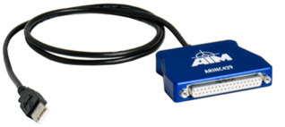
The ARINC 429 plugin (GInsARINCPlugin) extends a Q.station controller with support for ARINC 429 communication. Using the AIM ASC429-x USB 2.0 SmartCable, data from an ARINC 429 avionics bus can be integrated directly into a Q.series data acquisition system for synchronised acquisition and analysis alongside other measurement signals.
ARINC 429 input channels are mapped to the controller's virtual variables, allowing ARINC words to be sampled, processed, and recorded together with Q.series measurement data on a common time base.
Installing the GInsARINCPlugin
For installation instructions, refer to Installing a Plugin.
Configuring ARINC 429 Data Acquisition
Configure the GInsARINCPlugin in GI.monitor
Open GI.monitor from the GI.service user interface by selecting Tools > GI.monitor from the system tray.
-
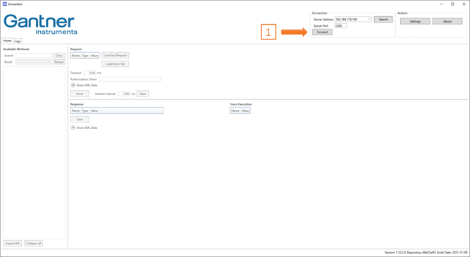
Enter the controller IP address in Server Address, set Server Port to 1200, and click Connect. If you do not know the IP address of your controller, use the Search button to find all controllers connected to your network.
-
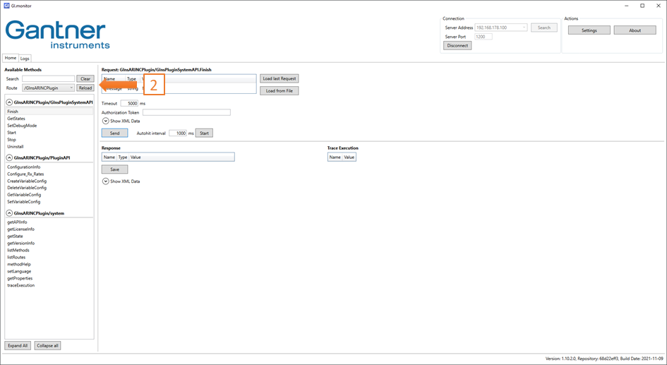
Click Reload next to the Route drop-down list, then select /GInsARINCPlugin.
-
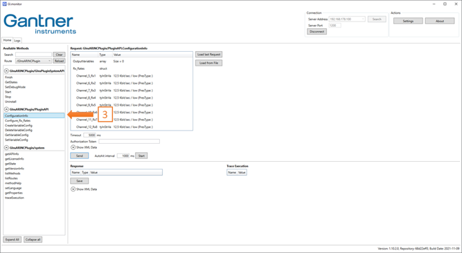
Navigate to GInsARINCPlugin > PluginAPI and select ConfigurationInfo. The current configuration stored on the controller is displayed. If the plugin has not been configured previously, the default values are shown.
-
Select Configure_Rx_Rates and set the required data rate for each ARINC 429 receive channel to 12.5 kbit/s (low speed) or 100 kbit/s (high speed). Click Send to store the settings on the controller.
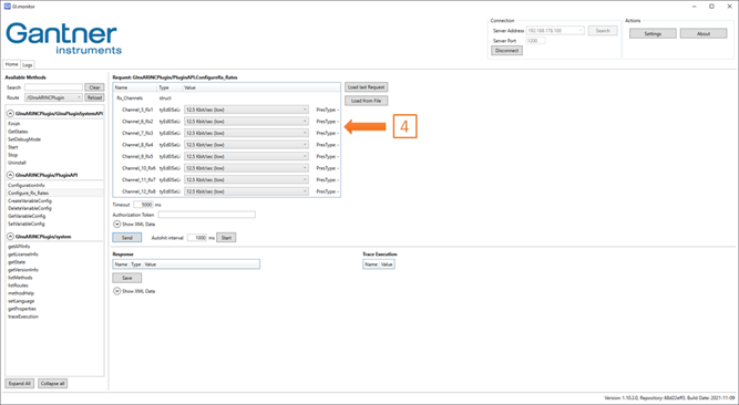
▶️ When using the AIM ASC429-12, channels 1–4 are assigned to ARINC 429 data transmission, while channels 5–12 are assigned to data reception. The GInsARINCPlugin currently supports receive (Rx) channels only; therefore, only channels 5–12 can be used with the plugin.
Configure ARINC 429 Receive Channels
-
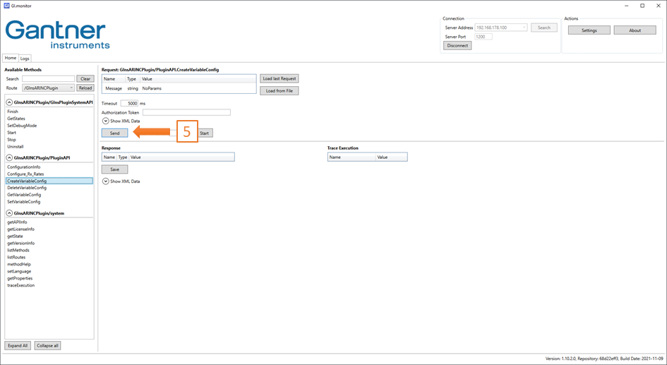
Select GetVariableConfig, select the ARINC word to be added, and click Send. Repeat this step for each ARINC word that needs to be acquired by the controller.
-
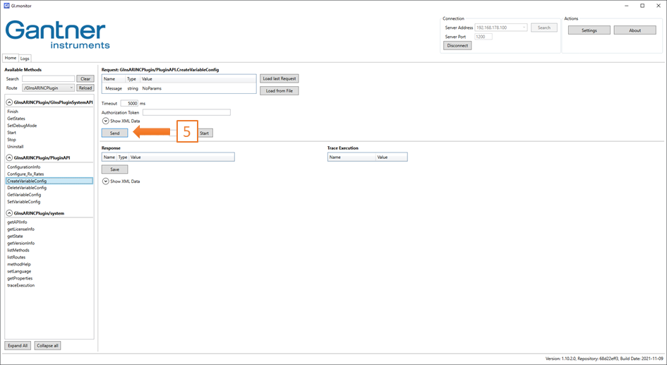
Select the required ARINC word under GetVariableConfig and click Send to retrieve its current settings. Then select SetVariableConfig and configure the required parameters for the selected ARINC word.
To check the number of ARINC 429 words currently configured, select GetVariableConfig. In the example below, four ARINC 429 words are configured by default.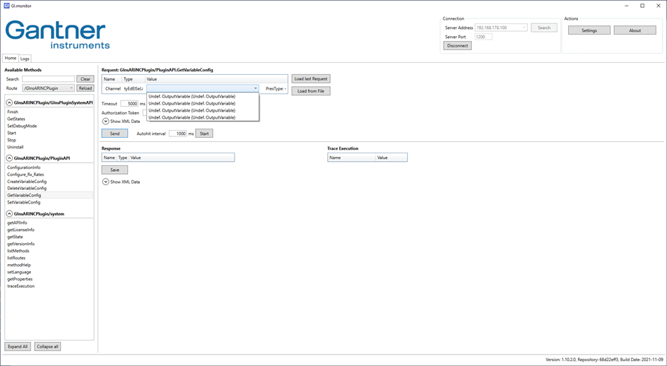
To remove an ARINC 429 word from the plugin configuration, select DeleteVariableConfig, choose the ARINC word to be deleted, and click Send. -
Select GetVariableConfig, choose the ARINC 429 word you want to configure, and click Send to retrieve its current settings. Then select SetVariableConfig to modify the configuration of the selected ARINC 429 word.
For each ARINC word the following parameters must be set:-
Channel
The ARINC 429 receive channel connected to the transmitting device. -
GIns_VariableName
The controller virtual variable to which the received ARINC 429 word is written. For information on creating and configuring virtual variables, refer to the controller manual.
▶️ The controller virtual variables must be created before configuring the plugin, as the plugin automatically detects the available virtual variables and makes them available for assignment to the ARINC 429 words.
▶️ Configure the virtual variables as Setpoint variables and set Data Direction to INPUT / OUTPUT. -
Label
The Label identifies the ARINC 429 word on the data bus. Each label must be unique but does not need to be configured in consecutive order in GI.monitor. Enter the label as a three-digit octal value, for example 273.
Bits 1–8 of the ARINC 429 word contain the Label, also known as the Information Identifier. The label is represented as a three-digit octal value, providing up to 256 possible labels (000–377). Within the ARINC 429 word, the label is transmitted with its most significant bit (MSB) in the least significant bit position. -
Length
The number of bits used to represent the data field within the ARINC 429 word (see also Section 5.4). -
Scale
The Scale Factor is used to decode the ARINC 429 data value (see also Section 5.4). -
Type
Identifies the data encoding format used to decode the ARINC 429 data value (see also Section 5.4).
-
-
After configuring the ARINC 429 word, click Send to write the updated plugin configuration to the controller. If the configuration is applied successfully, the response “Configuration changed successfully!” is displayed.
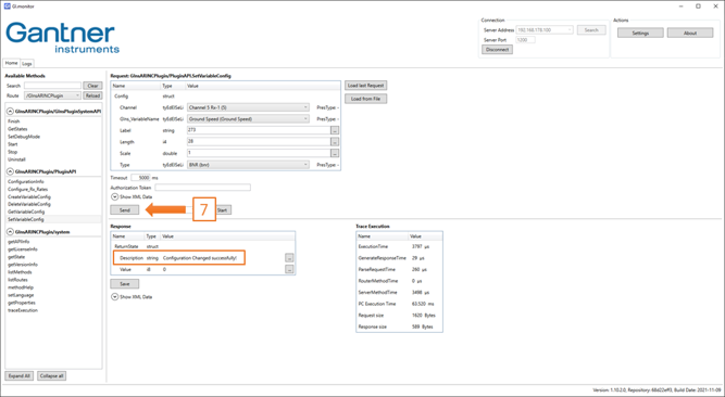
▶️ If an error occurs while sending the new configuration to the controller, the changes may not be saved. To avoid re-entering all parameters, click Load last Request to restore the most recently entered configuration.
ARINC 429 Data Formats and Decoding
ARINC 429 supports several data encoding formats within its 32-bit word. The Label (bits 1–8) identifies the parameter represented by the word, while the corresponding ARINC 429 definition specifies how the data field (typically bits 11–29) is interpreted. For measurement and data acquisition applications, the most commonly used encoding formats are BNR (Binary Number Representation), BCD (Binary-Coded Decimal), and discrete data.
BNR (Binary Number Representation) Decoding
BNR is a commonly used ARINC 429 data format in which the data field represents a binary numerical value. Figure 5-1 shows the general BNR data format.

Bit 29 is used as the sign bit, where 1 indicates a negative value or an equivalent directional state such as South, West, Left, From, or Below. Bit 28 represents the most significant data bit (MSB) and corresponds to ½ of the configured scale factor. Each subsequent bit represents half the value of the preceding bit; for example, Bit 27 represents ¼ of the scale factor, Bit 26 represents ⅛, and so on.
Plugin settings
-
Type
Set to bnr to decode ARINC words in binary format. -
Scale
Specify the scale factor (range) used to decode the binary data. The decoded value is calculated by applying the corresponding binary weighting to each data bit and summing the resulting values. -
Length
Specify the number of bits used to represent the data value, excluding the sign bit.
BCD (Binary-Coded Decimal) Decoding
BCD is another commonly used ARINC 429 data format. In BCD encoding, each decimal digit is represented by a group of four binary bits. The data field can contain up to five BCD sub-fields, with each sub-field representing one decimal digit.

The most significant BCD sub-field contains three data bits and can therefore represent a maximum decimal value of 7. If the required most significant decimal digit exceeds 7, bits 27–29 are set to zero and the next BCD sub-field is used as the most significant digit.
Plugin settings
-
Type
Set to bcd to decode ARINC words in binary-coded decimal format. -
Scale
Specify the scale factor (range) used to decode the BCD data. The decoded value is multiplied by this factor, for example 0.1 or 100, to obtain the final engineering value. -
Length
Specify the number of bits used to represent the data value.
Raw ARINC 429 Data
Raw data provides the ARINC 429 word without decoding or converting the data field into an engineering value. The underlying 32-bit ARINC 429 word is provided directly for further processing or analysis.
Plugin settings
-
Type
Set to raw to read ARINC words in raw format without decoding. -
Scale
Not used. - Length
Not used.
Frequently Asked Questions About ARINC 429 Data Acquisition
What is ARINC 429 data acquisition?
ARINC 429 data acquisition is the process of receiving, decoding and recording data transmitted over an ARINC 429 avionics data bus. With Gantner Q.station, ARINC 429 data can be acquired alongside analogue, digital and other Q.series measurement signals for synchronised analysis.
How can I acquire ARINC 429 data with a Gantner Instruments Q.station?
Connect an AIM ASC429-x interface to the Q.station and configure the GInsARINCPlugin. The plugin receives ARINC 429 messages, maps selected labels to Q.station virtual variables and decodes BNR, BCD or raw data for synchronised acquisition with other measurement channels.
Which ARINC 429 data rates and formats are supported?
The GInsARINCPlugin supports ARINC 429 low-speed communication at 12.5 kbit/s and high-speed communication at 100 kbit/s. Received ARINC 429 words can be configured by label and decoded as BNR (Binary Number Representation), BCD (Binary-Coded Decimal), or raw data.